16

A small shielded loop is an antenna with a loop of wire, smaller than 1/10th of a wavelength in diameter, also surrounded by a shield. Often, they are constructed from coax. There is a gap in the shield somewhere. Feedpoint arrangements differ among implementations. Here's an example from the 1988 ARRL handbook:

shielded loop

Here are more examples, these actually designed as magnetic field probes for compliance testing:

enter image description here

Such antennas are said to be quieter than ordinary small loops, and thus ideal for receiving, and popular for HF direction finding.

However, why? Why does the addition of a shield actually do, and why is it desirable?

Kevin Reid AG6YO
  • 25,080
  • 7
  • 55
  • 106
Phil Frost - W8II
  • 52,635
  • 8
  • 91
  • 225

4 Answers4

6

A "shielded loop antenna" is a very misleading name. It isn't an antenna, with a shield. It's an antenna made from a shield, with a feedline inside it.

It's commonly stated that the shield blocks electric fields and not magnetic fields. But that's false: it's physically impossible. That's not to say that a shielded loop antenna has no merit beyond an unshielded loop antenna, though. The "shield" makes an excellent, broad-band, low-loss, easily fabricated balun.

There's an analogous problem with dipoles also. If we want to feed a dipole with coax, we need a balun to prevent common-mode currents on the feedline, because if there are common-mode currents on the feedline, the feedline is part of the antenna.

We could build a magnetic loop antenna like this:

schematic

simulate this circuit – Schematic created using CircuitLab

The feedline is balanced, and the antenna is symmetrical. Like a dipole with a balanced feeder, there are no common-mode currents and the feedline will not radiate, provided the surroundings are also reasonably symmetrical.

But we want a coax feedline.

There is only one place to connect the coax that won't result in common-mode currents: immediately opposite the feedpoint. If we do this, then any common-mode currents will cancel at the feedpoint. With any other arrangement, common-mode currents can couple into the feedpoint, so the feedline will be part of the antenna.

enter image description here

But then how do we get the end of the coax to the feedpoint? The solution: make the antenna from tubing, and run the feedline inside the antenna. Because RF currents travel on the surface of the antenna, what happens inside the antenna is irrelevant to the operation of the antenna. Electrically, it looks like an ordinary loop antenna made from fat wire.

enter image description here

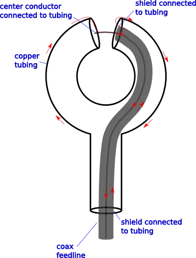
Modern Antenna Design by Thomas A. Milligan describes this as a natural balun (though, I've never seen that terminology used elsewhere):

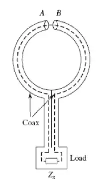
A natural balun feeds the coax through a loop antenna to the feed point where the outer shield is split and the center conductor jumps the gap to connect to the outer shield of the coax. At this point the currents flow on to the outer shield and radiate. By moving an equal distance along the coax until the two halves meet, we can connect the feed coax and not have current flow down the outside. The currents flow in opposite directions along the loop and cancel at the connection. From a circuit point of view, the connection point is a virtual short circuit to the balanced mode similar to a folded balun at its connection point. In a similar manner, on a folded dipole we can connect the feed coax to the middle of the shorted dipole and form a natural balun.

If we simplify the construction a bit and double the coax shield as the tubing, this type 2(d) from the question.

As it is, this design has a coax feed and no problems with common-mode currents. However, if one wants to add a capacitor to resonate the antenna at the operating frequency, or a matching network, one must be careful to preserve the current balance of the antenna. The ARRL design is notably horrible at this. However, we are getting away from the topic of the question, so I will suggest reading W8JI on small magnetic loops for a more detailed discussion.

Phil Frost - W8II
  • 52,635
  • 8
  • 91
  • 225
2

This is extensively and accurately covered in a great page by W8JI. It starts:

Small Receiving Loops

Small loops are often referred to as "magnetic radiators". Folklore claims a small "shielded" loop antenna behaves like an electrical sieve or filter, sorting "good magnetic signals" from "bad electrical noise". Nothing is further from the truth! At relatively small distances a small magnetic loop is more sensitive to electric fields than a small electric field probe.

Phil Frost - W8II
  • 52,635
  • 8
  • 91
  • 225
tomnexus
  • 12,365
  • 17
  • 36
2

The short answer is that the shield becomes the actual antenna. It's addition makes it easier to construct a balanced loop which has deep nulls broadside to the loop. These nulls would obviously be helpful in fox hunting / direction finding.

The long answer follows:

First of all the picture included from the 1988 ARRL Handbook has been shown to be a flawed design. Current balance is critical to the performance of the antenna and that one has the shield gap next to the feed point. So any current flowing on the outside of the feedline flows into one side of the loop where it is coupled to the inner conductor.

The best location for the gap is opposite the feed point as shown here:

Balanced Shielded Loop Antenna

The antenna works when EM fields excite on the shield's surface. Skin effect isolates the outer shield wall from the inner shield wall. Across the gap, the current on the outside of the shield produces a voltage, and that voltage in turn excites a current flow on the inner wall of the shield.

The current flowing on the inner wall of the shield creates a current in the inner conductor through induction field coupling, and that current (and voltage) is coupled to the receiver feedline.

EDIT: to clarify the use of the shield.

At HF frequencies loops are subject to what is know as the antenna effect because their size is a only a fraction of a wavelength, and they can pick up interference from a signal that is derived from the electric, rather than the magnetic, field. This distorts the loop's directional pattern, making shallow side nulls, if any.

To reduce the antenna effect, the loop can be shielded as discussed here and shown in the illustration I linked above. This electrostatic shield balances the loop by making sure that all parts of it will have the same capacitance to ground.

The shield also protects the loop from the induction field created by wires and other metal objects in the antenna's near field (up to λ∕2π away). These items can take energy from a passing wave and produce magnetic fields that can induce spurious voltages in the loop. This energy is reactive (not radiated) and a product of the transformer effect; it fades rapidly with distance (inverse cube-power law).

This is in contrast to the radiation field, which is the part we are interested in, made up of electrical and magnetic fields at right angles to each other and originating in the antenna's far field (> 2λ). The power of this field always varies according to the inverse-square law.

The shield over the loop antenna will not appreciably decrease the amount of magnetic flux that passes through (and links with) the loop when a wave goes by as long as it is not complete (i.e., shorted to itself). A gap must be left or the shield would form a shorted turn and it would reduce the magnetic field linking to the loop so that no signal could be received by the center conductor. Using the gap, alternating currents can be induced in the metal shield, and voltages will be induced in the internal wire.

You can also use the antenna effect to intentionally detune the loop with second small antenna (usually a vertical). This creates a pattern where there is only one null. This would be in the plane of the loop, off one of the ends, rather than the sides. This is also useful for direction finding.

References:

WPrecht
  • 6,540
  • 22
  • 43
1

The shield prevents (or greatly reduces) influence of the electric field component of the received signal, making the loop effectively a "pure magnetic" antenna. Shielding makes the antenna "quieter" than an unshielded loop or whip antenna by preventing the capacitive coupling of localized noise sources. It is particularly effective in shielding against the intrusion of impulse noise from power line arcs, light dimmers, fluorescent lights and television "buzz".

HarveyB
  • 143
  • 5