4

I'm considering building multi-turn wire loop receive antennas for a blitzortung.org lightning detection receiver. It has three separate channels for H-field antennas, operating simultaneously.

Typically, only two orthogonal loops in vertical planes are made and co-located, e.g like:

two orthogonal multi-turn wire loops in vertical planes, from skywarn-slm.at

Having enough real estate available this time, I wonder if there could be any advantage in placing loops several meters apart. Aren't directional nulls suffering from the close neighbour - other loop? (possibly resulting in a poorer SNR for the given loop, if a near noise source would be otherwise in a deeper directional null)

Same question applies for adding a third, horizontal loop. Are there any advantages in not using the same mechanical frame? When co-locating, is there anything about the feeder routing to consider? (extremely: one could route the feeder of horizontal loop in question right along the side of a vertical loop).

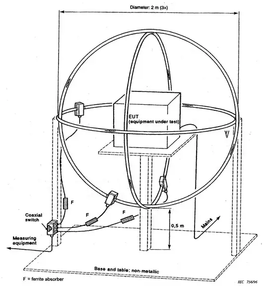
I saw three colocated orthogonal loops elsewhere, but that was quite a different application. There, only one of loops is connected to the receiver, others are open-circuit.

And lastly, would same considerations (from the answers to come) apply if shielded loops are used?

Mobius loop:

Mobius loop

Mike Waters
  • 8,201
  • 4
  • 19
  • 51
Xpector
  • 143
  • 3

3 Answers3

2

The lightning detection antennas are not used in any sense to triangulate or to direction find through any other method such as phasing. The three antennas are there simply to provide quasi 360° detection of lightning events. The actual direction finding is accomplished by analyzing the timing of detected lightning events from multiple sites using GPS time stamping and calculating time of fight by comparing data from multiple stations. In other words, if there was only one receive site in North America, no direction finding could be done for that region. In fact, it is acceptable to have a station with just one antenna - it simply may not be as sensitive to lightning events from certain directions.

With this as the background, feel free to spread out your loops if that works for you. Many people don't have that luxury which is why they have the creative colocated loops.

The "Blue" receiver version, the latest, has differential preamps so do not use any type of balun between the antenna and the preamp. You could place a wound coax/toroid type balun on the feedline to the receiver but keep in mind that you are dealing with very low frequencies so the typical amateur radio designs will not work well.

The shielded loop antenna is not the type that hides the feedline. They are using the split shield design to form a so called H field antenna (which has nothing to do with receiving only the H field!). If you decide to use such an antenna, follow their construction notes. They are sloppy on the description of where the break in the shield should be. I would recommend it be placed exactly in the center of the circumference in order to provide an optimum differential feed.

Glenn W9IQ
  • 18,688
  • 1
  • 25
  • 55
2

FORGET the third horizontal (yellow) loop antenna!

I finally disabled mine because it caused me no end of trouble with noise pickup and thousands of spurious signals sent to the BT (Blitzortung) servers in Europe. Although it appears in the official documentation, I have not been able to find anyone who is using one. Most are using just two vertically-polarized loops 90 degrees apart. That's all that are needed.

A better way is to have three H-field (magnetic) loops, all vertical, 60 degrees apart. (That's what I intend to do.) Several BT stations are using ferrite rods purchased from the BT people in a delta configuration.


In the forum, the developers have since retracted any recommendations for a horizontal loop. It was one of those "Well, it seemed like a good idea at the time" things.

I now have two Blitzortung lightning receiver stations, 1977 and 2294. If you are a participant you can see the antenna on https://forum.blitzortung.org.

Mike Waters
  • 8,201
  • 4
  • 19
  • 51
1

A third, horizontal loop, will give you an antenna which is horizontally polarized and omnidirectional in azmith, with nulls in the up and down directions. Would this benefit a direction finder?

I wonder if there could be any advantage in placing loops several meters apart. Aren't directional nulls suffering from the close neighbour - other loop?

I wouldn't think so. Since the fields of each are orthogonal they have no effect on each other. Adding a third loop is just as orthogonal as the other two. Just rotate it 90 degrees and it's essentially the same thing.

Keep in mind also that if the antennas are a significant fraction of wavelength apart, the phase difference between them will make a directional antenna array. If the objective is detecting lightning strikes in any direction, this would not be productive.

When co-locating, is there anything about the feeder routing to consider?

I think antenna modeling or empirical testing is the best way to answer this. I'd guess putting chokes on all the feeders would be good practice to minimize their influence.

And lastly, would same considerations (from the answers to come) apply if shielded loops are used?

"Shielded loop" is a horrible name. It's really just a loop antenna made from a tube, with the feeder inside it. The hollow antenna means the feedline is invisible to the external fields, and thus it provides a solution to the problem of feeding a balanced loop with an unbalanced feedline. In effect, it's a balun.

However, a shielded loop might give a solution to the problem you'd otherwise have in feeding three orthogonal loops in a way that's radially symmetrical in azimuth. The feeder for the horizontal loop could run inside one of the vertical loops and thus be invisible as far as the operation of the antenna is concerned.

Phil Frost - W8II
  • 52,635
  • 8
  • 91
  • 225