7

A post on http://adsbexchange.com/forums/topic/beginners-2-cantenna-easy-diy-antenna-to-improve-rangeplane-count uses a $\frac{\lambda}{4}$ sleeve made of a pop can beneath a $\frac{\lambda}{4}$ wire protrusion made from the core of a coaxial cable (coax with shielding removed). The protrusion connects to an SMA F connector that's lodged in a hole through the base of the popcan which in turn connects to regular coax that emerges from the bottom of the pop can. enter image description here

My question is -- Why does the length of the sleeve (the pop can) matter considering that the coaxial cable enclosed by it is completely shielded?

EDIT : Considering the comments below RE: inclined ground plane. It seems to me that the desire of the author is to impedance match to 75ohm coaxial cable. See the image below: enter image description here

Marcus Müller
  • 18,064
  • 26
  • 50
Jonathan
  • 73
  • 1
  • 1
  • 5

8 Answers8

5

Lemma: this antenna is a dipole with one leg of it acting as a balun. Specifically, a bazooka balun (AKA sleeve balun).

Whenever you want to feed a dipole with coax, you have to do something about common-mode currents. The trick is, one way or another, to make the common-mode currents on the coax a high impedance. Hopefully there's a much lower impedance path somewhere (like, the dipole you're trying to feed) and so there won't be much common-mode current.

How does it work?

First, consider that differential-mode currents on the feedline are irrelevant to anything outside the feedline's shield since their associated fields cancel. For now, let's simplify the situation by ignoring the antenna and assuming an infinitely long feedline. And let's also ignore the inside of the feedline and consider it just a fat wire. Here's a simplified view, in cross-section:

schematic

simulate this circuit – Schematic created using CircuitLab

Further, the feedline shield and the can together form another coaxial transmission line, with the feedline shield as the center, and the can as the shield. We will call this the can-coax. This transmission line is shorted at one end, and open at the other. It's a quarter wavelength long, which hints this may be a quarter-wave transformer.

Next, consider that at the open end of the can, any common-mode current on the feedline must become a differential-mode current on the can-coax. Because, only a differential-mode current can possibly flow on the center of a coaxial transmission line.

So effectively, the common mode is in series with a shorted, quarter-wave stub:

schematic

simulate this circuit

By the properties of a quarter-wave stub, the short at one end is transformed into a high impedance at the other end. Thus, the common mode is in series with a high impedance. QED.

schematic

simulate this circuit

Meanwhile the outside of the can is free to function as a fat, tubular leg of a dipole. Put it all together and you get:

schematic

simulate this circuit

By virtue of being resonant at your frequency of interest, this antenna (like all dipoles) also functions somewhat like a filter, which can improve performance if your receiver has poor selectivity.

Like Marcus Müller says, this isn't a well-engineered design, and at best it's no better than a properly installed dipole or monopole. But if all you have is some coax and a pop can, it's at least easy and inexpensive to fabricate.

Phil Frost - W8II
  • 52,635
  • 8
  • 91
  • 225
3

Bah. Humbug. For reference, the picture on which they base this design:

Coaxial antenna

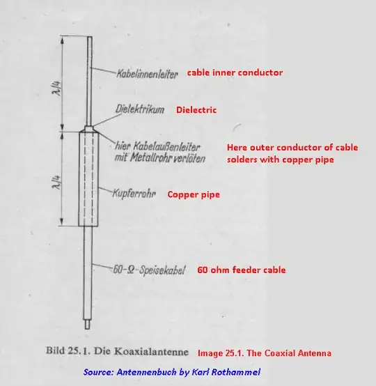
Is clearly simply a $\frac\lambda2$ dipole, meant for coaxes fed with a symmetric/ balanced signal, or producing one. The more alike the width of the tube and the upper copper antenna part are, the more "ideal" the dipole becomes.

In the way they use it here, the copper pipe is part of the ground part of an unbalanced receiver. So, this simply is not going to be great. What you want, as discussed in the comments, is a ground plane for a $\frac\lambda4$ monopole. And 45° radials is a well-proven, well-tested, pretty-close-to-perfect, foolproof way of implementing a seemingly endless ground plane.

For the length of the can in your picture to have effect, there would be the need for a current to flow in the lower parts of that. But that current can only flow if the can is not doing its job of simulating a perfect "E-field mirror" overly well (otherwise the energy "reflected" back into the upper half-space would be 100% of what incides at any point of the plane, and since the monopole is the only driven element here, it would surprise me if the currents induced at the part where the bends start actually help very much with making this a better antenna.

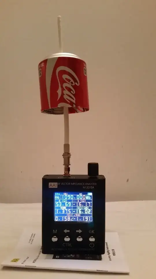
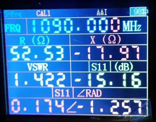
So, yes, they'll be getting better reception with that at 1090 MHz than with the stock TV antenna, but that's not hard. Simply replacing the $\ne\frac\lambda4$ monopole of that (e.g. by cutting it to the right length...) and placing the antenna on a conductive (magnetic, if possible, that's why it has a magnet in its pedestal) will probably do even better.


I rant about this far too often, but this is the year 2016. Antenna theory has been around for >100 years. And yes, physicists and EEs in their labs played and play around with all the conductive stuff they can get easily to build their antennas. So if someone shows up with an antenna design that seems new, expect them to use some sort of simulation, or an anechoic chamber with a reference antenna to measure against, before believing any advantage.

Really, EM simulation is not that hard these days, and with OpenEMS, it's available for free (I'm sure there's more ham-friendly software than that, though!), and I've met more than one person who claims to have designed the perfect antenna based on the Standing Wave Voltage Ratio at the desired frequency alone. Do you know what has perfect SWVR over a huge range of frequencies? A proper matched-impedance terminator.

For example, I have a friend who went to a rather well-known faculty at an US uni for a research internship, worked on and measured their newest antenna design idea, just to figure out the antenna was so inefficient, it was converting far more energy to heat than it was emitting radio waves. The prof wasn't disappointed at all – in the end, there's also needs for good absorbers and terminators, especially in isolation applications, so this was well worth keeping in the knowledge for future investigation or publication.

The point is you can't know if your antenna is good or bad without measuring its emission or at least simulating it. So, if not backed by solid data including a directivity and frequency chart, I simply apply "skepticism" as default reaction to antenna designs. And so should you.

Marcus Müller
  • 18,064
  • 26
  • 50
2

CANTENNA IS HYBRID OF 1/4 λ GROUND PLANE AND 1/2 λ COAXIAL DIPOLE.

In Coaxial Dipole, the sleeve (copper pipe) serves following functions:

(1) Lower limb of Dipole.

(2) Decoupling Sleeve/Sleeve Balun, but due to very narrow gap between coax shield and pipe, mostly filled with high loss outer plastic of coax, resulting in high loss.

In Cantenna the Soda Can performs following functions:

(1) Upper surface of circular bottom acts as ground plane disc.

(2) Cylinderical wall + lower surface of circular bottom acts as Decoupling Sleeve/Sleeve Balun, with a very large gap between coax shield and can wall, mostly filled by air, the losses are negligible.

Cantenna: Whip = 1/4λ, Dia of Can = 1/4λ, Height of Can = 1/4λ

abcd567
  • 389
  • 1
  • 2
  • 7
1

This is a quarter wave monopole antenna.

The current on the inner conductor is fed to the vertical wire, while the current on the (inside surface of the) coax shield is fed to the soda can.

The soda can, hopefully, acts as a ground plane. Normally ground planes are made with several wires, each 1/4 wavelength in size, and bent downwards near 45 degrees (this angle adjusts the antenna impedance to 50 Ohm, so it is matched to the coax and transceiver port).

There is lots of introductory material on these antennas. Here is one showing current distributions. Another one.

Juancho
  • 1,164
  • 6
  • 10
1

Simulation 2 of 2: CANTENNA Gain = 1.9 dBi SWR (75 ohms) = 1.5

abcd567
  • 389
  • 1
  • 2
  • 7
1

Frequency Sweep (From 100 MHz to 2500 MHz) of 1/4 Wavelength Cantenna.

abcd567
  • 389
  • 1
  • 2
  • 7
0

LINKS TO THESE POSTS REMOVED DUE TO ADVISE BY SOME MEMBERS

(1) June 07, 2014 - Sleeve Balun Costruction Details - Use of Soda can as sleeve Balun for a Coaxial Collinear Antenna.

(2) June 08, 2014 - A 1/2 λ sleeve dipole - Use of of same Soda Can as Sleeve Baloon for 1/4 wavelength monopole.

(3) The 1/2 λ Sleeve Dipole Renamed to "Cantenna", Aug 2014.

If you see my above posts in another forum, you will know that the 1/4λ x 1/4λ Soda Can was used as Sleeve Balun (Bazooka Balun).

I have originally given links to these posts, so that you can see the purpose & function of Soda Can, and also the performance test. Since some members objected to posting the link, I have removed these links.

The analysis of Phil Frost - W8II looks good.

Apart from theory, lot of users have found this antenna to perform very good, better than stock mag mount whip, cut to 1/4 wavelength, and placed over a food can made of iron.

abcd567
  • 389
  • 1
  • 2
  • 7
0

Results of measurements done today (January 24, 2017)

These results show that this antenna performs well at its designed frequency of 1090 Mhz. However it has low gain (≈ 1.5 to 2 dBi).

Test Setup
test setup

Frequency vs VSWR VSWR vs Frequency Sweep

R, X, S11,VSWR R,X,S11, VSWR

abcd567
  • 389
  • 1
  • 2
  • 7