18

In another question, commenters recommended that I look into adding a 1:1 balun to a dual-band dipole to eliminate the feedline as a radiator. As I understand it, a 1:1 balun also functions as a choke, but is more efficient because... reasons?

When I try to find plans to build a balun, they all seem to specify a frequency range of 1.6-30MHz. Why is that and how can I make a balun that will work on VHF and UHF?

William
  • 813
  • 1
  • 8
  • 19

4 Answers4

10

Let's clarify some terminology: a balun is any device used to convert between a balanced system (ladder line, dipoles) and an unbalanced one (coax, vertical monopoles). There are a lot of ways to make a balun, and a common-mode choke is one of them. A choke can also be used in balanced to balanced, or unbalanced to unbalanced connections where suppression of common-mode currents is merited.

The choke approach (or "current balun" as you'll sometimes hear it described) is nice because it's small, easy to fabricate, broadband, and low-loss. "Small" is especially an advantage on HF where other balun designs would be huge.

Ferite-wound chokes can be done on VHF as well. Jim Brown, K9YC has some measured data on ferrites. Look for page 49. His data show that Fair-Rite mixes 31, 43, and 61 can all be made to work. He shows for a T240 core of any of those mixes, you can get about 600Ω on 2m with 2 turns, and 300Ω with one turn on 70cm.

However, the effective permeability of ferrites drops with increasing frequency, so it becomes difficult to get a sufficiently high choking impedance for the choke to function effectively as a balun. 300Ω isn't great but might be sufficient for some applications. You can always measure and see.

Alternatively, VHF wavelengths are small enough that other balun designs become practical.

One approach is to keep the system unbalanced all the way. If you have an unbalanced coax feedline, then put an unbalanced monopole antenna on it.

Antenne gp vhf 3.jpg
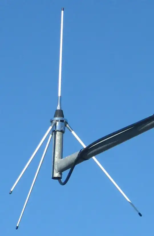
By F1jmm - Own work • Self-photographed, CC BY-SA 3.0, Link

The three drooping wires are the "ground plane". Drooping them increases the feedpoint impedance from the 37Ω of a monopole on a flat ground plane to 50Ω for a better match. Since the ground plane presents a very low impedance to the ground currents, that's where most of the current will flow. The coax common-mode is a relatively high impedance.

Some antenna designs which aren't simple monopoles use a "skirt" which looks like radials on a monopole. As in the monopole, the skirt looks like a low impedance ground plane, and the feedline is "hidden" under it.

Other designs are the folded balun, and the folded dipole. These designs work by getting the coax to attach at a ground potential point, while creating such a point through some clever arrangement.

A sleeve balun is another possibility. It uses a quarter-wave stub to insert a high impedance in the common-mode.

There some antenna designs out there that claim no balun is necessary. Sometimes it's true (the balun is intrinsic in the design) and sometimes it's not. Look for an antenna model that contains a feedline such as W8JI did with the J-pole. Or build the antenna and measure the common-mode current yourself.

Phil Frost - W8II
  • 52,635
  • 8
  • 91
  • 225
1

What you really want is a choke (often called current balun), as a voltage balun (i.e a transformer) will not isolate the feedline unless the antenna is in book-ideal conditions. The minimum misbalance in the dipole and the isolation is broken.

Don't have experience at those frequencies but I'd try a several series toroids as other have suggested to get a minimum of 2K commonn impedance at the frequencies of interest. If you can make it 5K much better.

0

If you're looking to minimize common mode current with a choke balun (like that returning from a balanced dipole down an unbalanced coax line), then you could slip a ferrite sleeve around the wire before crimping and heat-shrink it in place. These can be found at Mouser, Digikey, etc. Sleeves are much cheaper than clamp-ons.

Filter by your cable size (sleeve inside diameter), check the spec sheet to make sure it meets your MHz range and impedance requirements, and slip a few of these on your cable before crimping:

Update:

After some research I found that the Laird Performance Materials model #28B0686-000 which are quite inexpensive (available at Mouser for ~$0.26) provide the highest impedance per length ferite bead:

  • At 100MHz, 4" of bead provides 1.5kOhm (17 beads)
  • At 300MHz, 1.8" of bead provides 1.5kOhm (7 beads)

Theoretically you need fewer beads at higher frequencies, but only 100MHz and 300MHz values are listed on the datasheet. They could curve back down after a peak impedance so I'm hoping UHF is still >1.5kOhm at ~2" of bead.

Physical dimensions are:

  • ID: 9.52mm (0.375")
  • OD: 17.42mm (0.686")

so they will fit nicely over any cable smaller than LMR240/RG8x and can be water tight with ~3/4" adhesive heatshrink.

(Note: I'm not affiliated with Mouser in any way, just linking for what we are ordering in case it helps someone else!)

KJ7LNW
  • 879
  • 5
  • 13
-3

There is one easy answer, a balun is a transformer! - a choke is a choke!

Forget you ever heard the term "choke balun".

I'm sure you know balun stands for BALanced to UNbalanced. A 1 : 1 balun can be used to match a coax to an equal value impedance, balanced line.

A simple choke (one to eliminate common mode currents - CMCS) can be made by winding 25 feet of coax around a one gallon ice cream container. They have a slight taper, making it easy to remove the coil after winding and securing with wire ties in 4 places or so. Note the number of turns is not the critical factor here; rather the length of coax used. This should be effective from 1.8MHz and up.

Phil Frost - W8II
  • 52,635
  • 8
  • 91
  • 225