4

All antennas are a compromise. Are there any antennas that in free space perform strictly worse than an isotropic antenna would? Or a simple flat ground model?

This is what has been bugging me. I am a very new ham, especially with HF. I only have my technician license. I have a Xiegu G90 radio and was using a random wire antenna. I've seen all the articles about best lengths for random wire antennas. At some point, it occurred to me that while these may have a reasonable SWR that can be tuned on most bands, it doesn't necessarily mean they've got good gain.

I've tried finding data on this and it's hard. Either I get extremely basic results about half the half wavelength antenna is good or I fall into the black hole that is modelling software (and I don't want to try and figure out how to get that running on Mac/Linux, much less learn it for something simple). One thing I stumbled on though is that it is mostly the shape of the lines that changes. Sure, there may be more desirable shapes and less desirable ones, we don't want to point directional antennas straight down for example. But when you sum the gains in all directions, will it always be equivalent to an isotropic antenna?

I hope that makes sense. Basically I'm asking are there lengths or shapes of antennas that are actually doomed to be bad no matter how you use them. What are good lengths for random wire antennas if you want to get good gains? Or at least gains that aren't awful?

Captain Man
  • 141
  • 2

4 Answers4

2

Random Wire Antennas on HF Bands

When delving into the world of random wire antennas (a really bad and misleading terminology!) for HF bands, it's easy to get frustrated by the lack of definitive engineering information (and overabundance of bad or wrong information... such is the norm of amateur radio literature).

As a technician, you might be focusing on bands like 10, 15, 40, and 80 meters. The key to understanding random wire antennas is defining your goal, as performance and optimal design can vary significantly based on what you aim to achieve.

Defining Your Goal

For those interested in DX communications, the focus should be on radiating power at lower elevation angles just above the horizon. This approach is crucial for bands like 10 and 15 meters, where only signals with shallow angles are bounced off ionospheric layers. Lower takeoff angles are important for DX on all bands, including 40 and 80m. In contrast, individuals more interested in local rag chewing and nets (NVIS: near vertical incidence skywave) often design their antennas to radiate at higher angles, closer to straight up. These antennas are only useful on lower bands like 80 or 40 meters, as NVIS does not happen on 20m and higher.

Radiation Patterns and Elevation Angles

Integrating the radiated power density over a sphere covering the antenna and comparing it to an isotropic antenna is a common approach in electromagnetic studies. However, in practical radio communication, you want to direct your power into specific directions, including elevation angles. Even if you deploy a random wire antenna strictly vertically, where the antenna is omnidirectional in the horizontal plane, the vertical plane radiation pattern becomes a major factor.

When discussing antenna gain, whether the unit id dBi or dBD (dipole reference), the condition is very important, and the measurement (or simulation) condition must align with your operational goal. If you are on 10/15m or chasing DX, the gain should be evaluated between 10 and 35 degrees of elevation. If you are interested in regional contacts on 40 and 80m, you might be evaluating the antenna at 45 to 60 degrees elevation.

Optimal Radiator Lengths

The best lengths for the radiating element depend heavily on the quality of your ground soil:

  • Sandy or Rocky Ground: Optimal radiator lengths are around 0.6 wavelengths.
  • Saltwater Ground (e.g., fishing pier, ship): Optimal lengths are about 0.38 wavelengths or shorter.

For example, on the 10-meter band:

  • On sandy or rocky ground, a radiating element of about 6.3 meters (0.6 wavelengths) is effective.
  • On saltwater ground, a radiator length of around 3/8 of a wavelength (approximately 3.9 meters) works best.

Another limit is on the shorter end. You don't want to go much shorter than 1/4 WL, as the radiation efficiency drops. I personally don't like going below 1/8 wavelength, around which the performance drop is quite sharp.

Multi-Band Operation

Using a single radiator for multiple bands can be possible:

  • A 10-meter band radiator (about 6.3 meters long) can also function effectively on the 15-meter band. (It also works well on 12, 17, 20, and 30m, but you need to upgrade your license.)
  • For regional contacts on 80 meters and 40 meters, you can use a single inverted L on both bands with reasonable efficiency, as long as the length is longer than 1/4 WL on 80m and shorter than 5/8WL on 40m.

Antenna Configurations

Different configurations serve different purposes:

  • Vertical Deployment: Ideal for DX communications. This is the only good option on higher bands like 15 meters or 10 meters. This configuration ensures that the power is radiated at lower elevation or takeoff angles.
  • Inverted L Configuration: Suitable for regional rag chewing and nets on 80 meters and 40 meters.

Ground Soil Quality

The quality of your ground soil significantly impacts antenna's optimal design and its performance:

  • Elevated Radials: Essential for improving performance, especially in dry or rocky ground conditions.
  • Seawater Ground: Limits the radiator length to about 3/8 wavelengths due to high conductivity, but the whole antenna system performs much better (colloquially called "salt water amp.")

Antenna Simulators

While there is an antenna simulators available on macOS, it may not be well supported (not quite up-to-date). For random wire antennas used strictly in a vertical configuration with elevated radials, understanding performance from known examples can often suffice without custom simulations.

Personal note

I am primarily interested in DX, so vast majority of my antennas are optimized for 30m and higher and straight up vertical, with elevated radials. (I have a mast that supports a full size vertical on 40m.) When I do 40m/60m/80m while operating from mountain summits (SOTA), the operation is limited to mid-day anyway (when there is no DX propagation), I add a horizontal element at the top of my vertical to convert to inverted L. Either way, my vertical antennas make plenty of regional contacts with enough signal strength for rag chewing in CW, despite being optimized for DX. However, if I were focusing on the regional contacts, I would go straight to a horizontal or inverted L antenna.

Ryuji AB1WX
  • 2,962
  • 1
  • 1
  • 26
1

But when you sum the gains in all directions, will it always be equivalent to an isotropic antenna?

Nope! Real antennas have losses; some more, some less. Loss means that RF energy gets converted to heat.

And you mentioned impedance matching in your tags: some antennas are well-matched to your transmission line, which you use to connect to that antenna, at the frequency you want to work at, and others are not.

Basically I'm asking are there lengths or shapes of antennas that are actually doomed to be bad no matter how you use them.

Hm, antennas that are very short compared to wavelength are doomed to be inefficient, physically. But take the same shape and scale it up, and at some point it will be less bad.

You'd also think that shapes that take your wire and knot it are universally bad, but a few very high-bandwidth antennas essentially look like a ball on a short podest. It's again a question of your goals, and what the size of your ball of yarn is.

So, nope, no general terms. In some cases, having a few turns of your wire wound around a stick will make the antenna better matched at the frequency you want to work; in some cases it'll do the opposite. In some cases, spanning a triangle would be a really bad idea, in some cases it's brilliant. The list goes on forever.

What are good lengths for random wire antennas if you want to get good gains? Or at least gains that aren't awful?

If dipole, then half-wavelength in total. If monopole, then quarter-wavelength in total. A conductor running through "material" (say, through the leavy top of a tree, or along a concrete wall) will look a bit longer to electromagnetic waves than it mechanically is.

You're showing the right attitude here: you're aware that to make quantitative statements, you'd probably have to simulate. (and the effort estimation that this might not be worth it: spot on; there's often too many confounding effects, because your antenna doesn't float in the void of space.) And the idea that you start somewhere, and then experimentally improve random wire antennas is also very true. As the name suggests, they deal with the problem of not being able to be perfect by being random. Randomness isn't always good on first try!

Marcus Müller
  • 18,064
  • 26
  • 50
1

Are there any antennas that in free space perform strictly worse than an isotropic antenna would?

Yes, all of them. And also, none of them.

Because first, you must define "worse performance." By definition, it's not possible to have less directivity than an isotrope. So if "directivity" is your measure of performance, then all real antennas will have "better not worse" directivity than an isotrope.

If instead you mean "possible to have 0 or negative gain with respect to an isotrope in every direction," then yes. A dummy load (none of which are perfect) will do this, as do many compromise antennas made for small spaces (shout out to my apartment dwelling peeps).

At some point, it occurred to me that while these may have a reasonable SWR that can be tuned on most bands, it doesn't necessarily mean they've got good gain.

You've absolutely hit the nail on the head here! Let's hammer it home:

SWR is merely a measure of power transfer efficiency and communicates zero information about gain. Both the 50Ω resistor (all RF energy dissipated as heat) and the isotropic radiator (all RF energy radiated from a point source) have a theoretical SWR of 1:1. Hopefully this illustrates that SWR can give you no information about where the energy goes after the transfer.

Consider that the perfectly isotropic radiator is on one end of an RF performance continuum (where highest performance is defined as all RF energy sent into the system is radiated), and the 50Ω perfect non-radiator is on the other end, both with SWR 1:1. All real antennas, regardless of physical- and radiation-geometry will be somewhere between the two. The sums of their radiative gain in all directions + heat dissipation = the amount of power input to the antenna system.

A worse SWR than 1:1 just means that some of the energy/power is not even making it into the antenna system.

webmarc
  • 4,757
  • 1
  • 19
  • 45
1

I guess Captain Man hasn't found any of the explanations satisfactory yet. So to your first contention, Captain Man:

All antennas are a compromise.

No, not if they are purpose built.

Are there any antennas that in free space perform strictly worse than an isotropic antenna would?

That depends on what you mean by worse in your application. I would say an isotropic antenna is the worst in all cases because I'm not trying to place radio energy in all directions, I want it in certain directions, to the detriment of other directions.

Or a simple flat ground model?

If you're talking about a ground plane antenna, I consider these almost as bad as a theoretical isotropic antenna due to ground losses.

I've seen all the articles about best lengths for random wire antennas. At some point, it occurred to me that while these may have a reasonable SWR that can be tuned on most bands,...

These "best lengths" are usually because someone has worked out how to get a particular length of antenna to be within the tuning range of either a radio's built-in tuner if it has one, or an external tuner, since by design, tuners can only tune-out a certain amount of mis-match.

... it doesn't necessarily mean they've got good gain.

Gain is relative, and affected by several items, first, the antenna's proximity to ground, because the the Earth can be a reflector and an absorber of energy, and to the extent it acts as a reflector, your pattern is impacted by the extent of the reflections are in or out of phase with the currents on your antenna. Watch this video of an antenna in free space, as the number of wave lengths on it increases, and see how it's pattern changes. Varying Antenna Lengths in Free Space
You'll notice lobes are created that will have very high gain in those particular directions, and conversely, deep nulls in other directions. Now, keep in mind this is a free space model, here on Earth, your lobes and nulls will be much more of a compromise, and as in one of my antenna designs, even my null has about 7dBi gain, while my main lobes have 12dBi gain...not a bad compromise; what I did sacrifice was sending energy straight up into the sky, but that is where it is useless to me.

Remember, your particular antenna performance in any given band is going to be affected by how many wave lengths long it is on that band, it's height above ground at every point on the antenna (I'm looking at you slopers), the characteristics of your Earth at your location, and it's overall design. Here's a tunable end-fed antenna that will work multi-band without a tuner with a 49:1 or better yet, a 64:1 UnUn. K2NYL Tunable Block & Tackle EFHW Antenna 
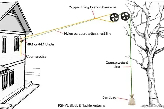
You need to make provision to have your counterpoise wire, be easily changeable or adjustable to get the widest range of bands; the lengths will be determined by experimenting with pulling the main radiating element in and out, adjusting for the lowest SWR in the middle of a given band, and then cutting back, or otherwise changing the length of the counterpoise to get to the lowest possible SWR; you may also find you are still adjusting the main radiator at the same time as you are moving your voltage feed-point every time you adjust the length of either element. Your antenna's lowest band will be where your main radiating element is a little less than a half wavelength in length of a given band. I can get 1.6:1 SWR on 80M, on my vertical 40M antenna, by lengthening the main radiator from ~65' to ~67', but that's where I run out of wire. To make this design adjustable, you need flat-strap braided copper; 3/16" is strong enough for an 80M design, or 1/4" is strong enough for a 160M antenna (~75M in length). This design makes a "random" antenna, much less random, because you can tune it without a tuner, and you can tune-out the random environmental effects of your particular location/situation. There's plenty written about end-fed halfwave antennas, so I'm not going to go into the design elements here, I'll only say that your counterpoise is typically about 0.05 of a wavelength for the band you want it to work on; with that said, my 40M counterpoise works just as well well on 20M and fairly well on 15M, but needs adjustment on 17M, 12M & 10M. Also remember, you don't have to shorten the main radiator of the antenna to 5M to use it on 10M, you just need to tune it a little so that it's resonant, and that may be three feet, in one direction or another, as compared with your overall length. You will have multiple current loops on the antenna, and that will give directionality to it, but that could be highly desirable if you orient the antenna in a way where those lobes are in a direction you find useful.

And keep experimenting with antenna software, it is a very useful modeling tool for patterns and understanding feed-point impedances for various designs. EZ-NEC 7 is free and has many sample antenna designs that you can modify and play around with until you get the hang of it.

Louis Seaman
  • 1,058
  • 3
  • 10