Shielded cables have long been used in radio communications to prevent RF interference and external noise pickup in microphone lines. However, shielding alone is often not enough, and proper RF interference protection requires a system-wide approach. This post explores the role of shielding, how microphone circuits have evolved over time, and why unshielded RJ45-based microphone connections are still widely used despite their apparent limitations.
Why Shielded Cables Are Used in Microphone Lines
Shielding is traditionally used to:
- Prevent RF pickup from strong transmitters
- Reduce induced noise from power lines, digital circuits, and other sources
- Minimize RF feedback loops, which can cause distortion and oscillations in transmitted audio
In classic radio setups, dynamic microphones were commonly used. These microphones contain no active electronics, meaning they were relatively immune to RF rectification effects, where strong RF signals induce unwanted currents in circuits. Shielding the microphone line was often sufficient to prevent interference.
However, as technology advanced, electret condenser microphones became more common due to their small size and low cost. These microphones include a small FET amplifier inside the capsule to convert the condenser element’s high impedance into a lower, more usable impedance. This change introduced a new problem:
The FET in the microphone can pick up RF signals, rectify them, and feed interference back into the microphone line.
This makes the entire microphone system more susceptible to RF pickup, requiring additional filtering and shielding strategies.
Incidentally, bipolar transistor amplifiers are much more susceptible to this effect of rectifying (detecting) the RF picked up by the signal line. Some circuit designers use the J-FET input stage in the microphone amplifier, even if the impedance is very low, for that reason. (The difference is that the J-FET gate pn junction is non-conducting, while the BJT base is always forward-biased in amplifiers, making the latter an effective half-wave rectifier.)
RF Protection: More Than Just Shielding
To properly protect microphone circuits from RF interference, manufacturers and radio operators employ several key techniques:
- Shielding the cable using braided shielding, foil, or shielded twisted pair
- Using ferrite chokes on microphone cables to suppress common-mode RF
- Adding shunt capacitors and series inductors to block high-frequency RF from entering the audio path
- Ensuring proper grounding at both the transceiver and microphone ends
Modern amateur radio transceivers incorporate these RF protection techniques on both the microphone and transceiver sides, but not all designs are equally effective.
Why RJ45-Based Microphone Connections Use Unshielded Cables
Many modern transceivers use RJ45 connectors for microphone inputs, and surprisingly, many commercial microphones and adapters still use unshielded cables. (Note: shielded cables are commonly available for high-speed Ethernet and other applications. They aim to reduce noise interference as well as cross-talk across pairs.) This seems counterintuitive given the importance of shielding for low-level audio signals, especially in RF-heavy ham environments.
A few reasons why unshielded cables might still be used:
- Cost and manufacturing simplicity – Unshielded cables are cheaper and easier to work with.
- Microphone circuit design compensates for interference – Some radios have built-in RF suppression, making external shielding less critical.
- Alternative shielding techniques – In flat ribbon cables, microphone lines may be positioned between ground, +V and control lines (all RF bypassed), providing partial shielding.
For strong RF environments, however, unshielded cables can be a weak point. Upgrading to shielded twisted pair (STP) cables or modifying the setup with RF chokes and additional filtering can help mitigate interference.
Keep in mind that radio communication systems typically do not require the S/N ratio level required by hi-fi audio equipment.
How RF feedback into AF happens
Because of the reasonably low signal impedance, short cable length, and modest S/N ratio required for radio communication, picking up AC hum or noise from nearby devices is rather easily mitigated. However, RF feedback is a bigger challenge, especially for AM and SSB transmitters. It is less problematic with FM due to the constant envelope. It can be problematic in CW mode due to a keying malfunction.
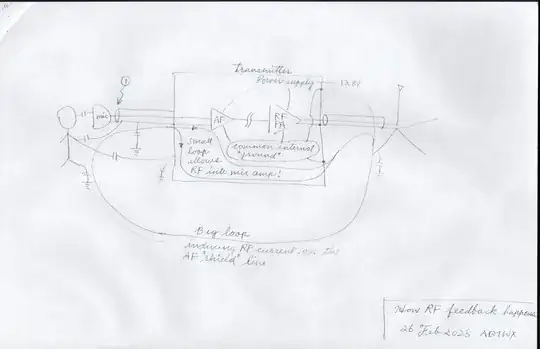
As you see in the diagram above, the common mode current in the entire station (big loop) is the major source of the RF current. [Note] Then, sharing the microphone signal ground with the shield (chassis ground) makes a fraction of the RF current divert into the mic amp circuit. No amount of shunt capacitors will fix this problem because it is a ground loop problem.
[Note] If the antenna is near the operating position, reactive near-field interaction is also a good possibility, in which case the antenna couples with the microphone cable through E and H fields directly. However, the rest of the mechanism and how to interrupt the feedback are analogous.
The ineffective use of shields fails to block RF feedback.
How to avoid the RF feedback
Separate the microphone signal ground from the shield (chassis ground), even if not a complete shield, is a good first step. By not using the shield as a signal path, the stray RF current goes straight to the chassis ground, not the mic amp. This may only be a modest reduction if the shield is only partial (like flat ribbon cables). Additionally, RF chokes at the mic amp input stage (on the circuit board) effectively interrupt the small (transmitter's internal ground) loop. However, RF chokes on the microphone cable outside the transmitter may be ineffective because environmental coupling can partially bypass that choke.

Using a shield as just a shield and not as the signal ground line is the correct way to use the shield. Once you pass signal current on the shield (i.e., use both ends of the shield), the potential at various places on the shield is not the same, and it loses the Faraday cage effect. In other words, picks up the noise and RFI more easily than carrying the return current / ref potential on a different line, depending on how you do it, of course. Shielded twisted pair is one of the best approaches, even if the signal is unbalanced.
For my stations, I use shielded twisted pair cables whenever possible for my radio setup, even down to the straight keys. The shield is connected only to the transceiver side, reducing the risk of RF entering the transceiver.
Also, using a very effective common mode choke on the feedline removes the source of the stray RF current and sends the transmitted power just to the antenna system. In order for this to be effective, the choke must be high impedance, not just the reactive part but also the resistive part. This "high impedance" is in relation to the impedance of the common mode loop circuit, not to the 50 ohms, so it is best to have north of 1000 ohm, or better yet, 2000+ ohm.


