I figure the transmitter has a 50-ohm pure resistive output and that the transmission line is 50-ohm as well. I think it's usually the antenna itself that actually needs to be tuned, yet it sounds like everyone places the tuner at the transmitter side. what are the effects and wouldn't it be better to have the tuner at the antenna? my guess is that the transmitter sees a "perfect" match and will have no complaints but that there are reflections from the antenna port going back and forth between the tuner and the antenna. i think this would create a power bottleneck where the transmitter could put out more power but the tuner/cable/antenna combo can't "absorb" that much power. i would think there are standing waves between tuner and antenna which will make it harder to send more power through as well as cause additional losses.
4 Answers
There are a lot of topics in this question, so let's take them one at a time.
I figure the transmitter has a 50-ohm pure resistive output
Not necessarily. You're probably arriving at this conclusion based on the maximum power transfer theorem. Which of these circuits delivers more power to the load resistor?
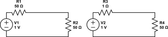
simulate this circuit – Schematic created using CircuitLab
What we can say is the manufacturer has designed the transmitter expecting a 50 ohm load, and they've also designed it to minimize their cost, thus maximizing their profit. This means when the load is 50 ohms the transmitter will be able to make its rated power while staying within the ratings of the components of the transmitter, the finals especially. But there won't be much margin for deviation, because that would increase costs.
When the load isn't 50 ohms this might subject the finals to too much current, voltage, or power. If we're lucky this means the radio just reduces power. If we're unlucky the radio doesn't reduce power, and the finals are damaged.
So we want the transmitter to see 50 ohms so it can operate as designed.
I think it's usually the antenna itself that actually needs to be tuned
Usually, but not always. Most radios these days are designed for a 50 ohm load, and 50 ohm coax is very popular. But there is also 75 ohm coax, and there are balanced feedlines between 200 and 600 ohms which are readily available.
Also, not all radios are designed for a 50 ohm load. In particular, older tube radios typically have a variable output network, so they will work with a whole range of loads. And although coax has been around since the mid-19th century, it wasn't really until after WWII that it became available to regular folk. Prior to that the most common feedline was some kind of balanced feedline typically with a higher impedance.
my guess is that the transmitter sees a "perfect" match and will have no complaints but that there are reflections from the antenna port going back and forth between the tuner and the antenna.
This is exactly right. The reflected power from the antenna encounters the tuner, and the tuner (if you've managed to adjust it so the transmitter sees a 1:1 SWR) re-reflects that power back at the antenna. The consequence of these extra reflections is usually (but counter-intuitively, not always!) additional loss in the feedline.
i think this would create a power bottleneck where the transmitter could put out more power but the tuner/cable/antenna combo can't "absorb" that much power.
Not usually. Under normal circumstances, the feedline and antenna are linear systems, which means waves can be superimposed indefinitely. What happens is that each reflection is independent of what's happening with other reflections at the same time.
However, linearity does break down eventually for just about any real system. To give one example, that additional loss in the feedline causes the feedline to become warmer. At some point it will become warm enough that the dielectric may melt, and the center conductor will short to the shield. Or, the voltage can get high enough to arc through the coax dielectric. It's pretty much impossible to get to this point with 100W and LMR-400, but 2kW and some really terrible RG-58 might. For broadcast stations in the megawatts, it's definitely a concern.
In summary, on purely theoretical grounds it usually is better to put the tuner at the antenna end of the feedline. However this requires making it weatherproof, and having some mechanism to remotely operate it, which makes it more expensive and difficult to install. Those downsides may or may not outweigh the benefit, depending on circumstances and priorities.
- 52,635
- 8
- 91
- 225
To make a long story short, if you are using 50 ohm coax with a 50 ohm radio, putting the tuner at the antenna is higher efficiency because it reduces losses in the coax caused by high SWR.
However, putting the tuner at the antenna has some huge disadvantages. It has to be weatherized. It is more prone to damage from lightning. It has to be remotely powered and possibly remotely controlled. If anything goes wrong, you have to pull down your antenna to service it, etc. It's much easier to just put the tuner next to the radio. Manual tuners (that need to be next to the radio) don't even need power.
Having said that, there are a number of antenna designs that integrate a simple cheap tuner into the antenna. These miss most of the disadvantages, and some don't even need to be powered.
However, the losses from SWR in the coax are usually not so bad that you can't operate anyway with a tuner at the radio, as long as you stick to under 100w and realize you might not be getting full power to the antenna. And as another answer pointed out, not all radios or feed lines are 50 ohms, so a remote tuner might not make sense in that case.
- 7,104
- 1
- 11
- 23
I'll add that a tuner is used for tuning, and tuning, for a single or small set of frequencies is often done at the antenna, usually by adding or adjusting a loading coil or adding a capacitive top-load or hat (etc.), usually done during antenna design, construction, or deployment.
However a tuner is used for a wider range of tunings, thus has additional reactive components and switching components that (1) weigh something and (2) are only used in some tunings for some frequencies. Thus a tuner has addition weight, often unneeded, that might involve some difficulty adjusting, maintaining, and hoisting stuff perhaps a hundred feet in the air, far away from the operating point, to an antenna's feedpoint.
But for some field antenna's the answer is both, as the feedpoint for a random wire or an end-fed (e.g. highly off-center fed dipole) and counterpose might be right at the transmitter (in SOTA ops, et.al.). So tuning with a tuner can be done at both the transmitter and the feedpoint, since those two points are colocated.
- 13,635
- 8
- 49
- 83
The conditions on a transmission line in terms of the line impedance depend on the characteristic impedance of the line and on the boundary conditions, which are in this case a transmitter at one end and an antenna at the other. In other words the source (radio + matcher) and load (antenna) both have an effect on what is happening everywhere on the line.
As mentioned in the question, if there is a mismatch at both antenna and radio ends of the line, then there will also be a two reflections bouncing backwards and forwards between both ends which interact with each other.
If the fed point impedance of the antenna doesn't match the characteristic impedance of the line, there will be a reflection at the antenna and the result is a standing wave on the line the voltage and current of which are out of phase with each other. This phase difference between voltage and current of the standing wave depends on the the value of reactance present in the impedance of the antenna.
If there is a reflection at the antenna feed point, then the impedance at any point along the line becomes a function of the distance from the end of the transmission line. If you position a matcher at the radio end, then when you adjust for lowest SWR, what you are really doing is adding a reactance which is opposite to that present in the antenna impedance such that phase difference between voltage and current on the line is returned to zero degrees. This removes the standing wave and the impedance everywhere on the line becomes the characteristic impedance of the line.
So to answer your question, using a matcher at the radio adjusted for a perfect SWR removes the standing wave from the line just as if the antenna were matched perfectly and there is no bottle neck and you get maximum power transferred from radio to antenna just as is the case for a perfectly matched system where a matcher is not required.
It seems many ham radio operators think that if you use a matching device at the radio end, then there is still a standing wave on the transmission line resulting in increased I²R losses, and it's better to place the matcher at the antenna, and this idea is false.
- 3,787
- 15
- 42