1

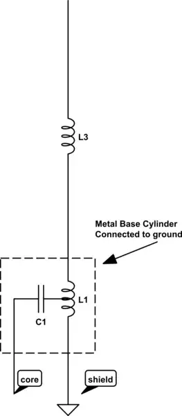
This is the insides of a common dual band antenna 2m/70cm, made by diamond or nagoya. its generally labelled as: 1/2 wave radialless (144MHz), 2 x 5/8 wave radialless (430MHz) Its meant to be ground independant.

Im trying to find the design name for the tuning/matching circuit at the bottom and how it works.

  • For example what stops the signal going down to ground at L1 rater than going up the elements ?
  • Does the coil below the C1 tap point provide the counterpoise/ground for the antenna, and the part of coil above act as matching/loading coil for lower element ?
  • calculators/plans around for this type or antenna ?
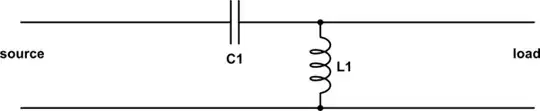
  • generally how does it work, im also trying to model it such as in 4nec2

schematic

simulate this circuit – Schematic created using CircuitLab

Brian K1LI
  • 7,960
  • 12
  • 34
Hayden Thring
  • 143
  • 1
  • 7

2 Answers2

3

This arrangement:

schematic

simulate this circuit – Schematic created using CircuitLab

is called an L-match.

Adding a tap to the inductor creates an autotransformer which allows an additional degree of freedom in the tuning network. It's useful here because the impedance of the half-wave element is much too high; the autotransformer steps it down to something closer to 50 ohms, reducing the mismatch that must be corrected by the L-match.

This is very similar to an equivalent circuit for a gamma match, the only difference being the autotransformer is flipped around.

Phil Frost - W8II
  • 52,635
  • 8
  • 91
  • 225
1

The matching circuit looks similar to the type of N:1 balun/unun used to feed an end-fed half-wave without too great an impedance mismatch. Except in this case L3 shortens the dipole at its center, and the portion below half of L3 is the counter-pose to the quarter wave section above half of L3.

hotpaw2
  • 13,635
  • 8
  • 49
  • 83