Everyone knows that balun stands for Balanced to Unbalanced and is an AC electrical device which can be used as an impedance transformer and is also used to convert an unbalanced or single ended AC system to a balanced or differential AC system and vice versa.
A common example of usage of this device is to enable an unbalanced coaxial transmission line to be used to feed a balanced dipole antenna split in the middle with the feed point in the center.
Very quickly, there are a few different types of balun :
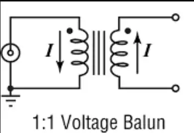
Voltage balun which behaves like an isolation transformer and removes the DC ground or common connection between input and output and allows the output to 'float'.
Current balun which allows conversion from balanced to unbalanced but with a ground or common connection between input and output thereby referencing one side of the balanced system to the same ground as the input.
Delay line baluns which used 1/4 wave length sections of coax cable as impedance transformers.
One of the desirable effects of using a voltage balun with coax and a dipole antenna for example is that because the balun is a low impedance device which blocks common mode current, all of the current present on the inside of the coax is transferred through the balun and no current can split up at the end of the coax braid and flow down the outside of the coax.
This prevents an undesirable effect commonly known as "common mode current on the outside of the coax" which basically makes the outside of the coax part of the antenna.
Because an RF choke can prevent current on the outside of coax just like a voltage balun does, confusion has arisen and there is a widespread belief that when used with an antenna an RF choke is a balun.
Unfortunately while both devices can produce one same result amongst many variables, this common misconception also confuses anyone trying to understand how antennas and transmission lines work.
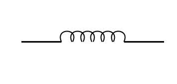
An RF choke is in fact not a balun and doesn't convert a balanced to unbalanced system at all, but rather is an inferior band-aide solution to get ridding of common mode current.
An RF choke can't be used on it's own as an impedance transformer, and if you use coax with a balanced dipole antenna and an RF choke in line to stop the common mode current on the outside of the coax problem, you still end up with an unbalanced dipole with one side which has a DC connection to the ground of the input, which is not the same result you get with a voltage balun which provides DC isolation between input and output.
Also it's far easier to get an acceptable common mode rejection using a proper balun to get rid of undesirable common mode current than it is to get the exact impedance required in an RF choke to block the same current, especially since the effectiveness of an RF choke is highly frequency dependent whereas a balun isn't as much.
Saying that an RF choke is a balun because both things block common mode current is the same thing as saying that a hammer is a brick because you can use both to bang in nails so let's all build our houses out of hammers, or sea water is the same as tap water because there are fish in both so it's ok to drink both, etc. !
The result is that there are probably many antenna installations out there with a dipole for the driven element that don't work as well as they could because one side of the antenna has a DC connection to ground causing an unbalance in what is supposed to be a balanced system, and with RF chokes which don't actually block that much common mode current, thereby messing up the radiation pattern and being more susceptible to local interference, where a real balun wouldn't have these problems.
Hope that all makes sense !
RF CHOKE

VOLTAGE BALUN

