7

So I'm developing my own SDR software from scratch (I like to "own" the code). The channel between the RF-to-USB hardware and the software is 192kHz sample-rate IQ audio samples. The degrees of freedom seem to include at least 4 frequencies and a switch. The 4 frequencies are: RF filter frequency, external tuner reference oscillator frequency, software complex multiplication oscillator frequency, software bandpass filter center-frequency (also filter bandwidth). Then select from I, Q, I+Q, I-Q, or abs(I,Q) for audio output. Then resample as necessary to match the audio output API.

So assume I set the 1st frequency (front-end RF filter) to the HF band of interest, the 2nd HF reference oscillator to the middle of some CW HF band. Now say I find a QSO 12.500 kHz up from the HF reference oscillator, and I'd like the resulting Morse Code audio side tone frequency to be 750 Hz.

Where do I set my software oscillator frequency for the complex multiplication and what do I want my software bandpass filter center frequency to be to hear Morse Code with the desired side tone? (Do I have 2 choices? If so, how to choose?) Which final IQ mux output do I select to feed the audio speaker?

Kevin Reid AG6YO
  • 25,080
  • 7
  • 55
  • 106
hotpaw2
  • 13,635
  • 8
  • 49
  • 83

2 Answers2

7

Implementing a CW receiver in an SDR is pretty much like implementing a SSB receiver.

You will tune the RF bits to some band of interest.

Next, you will multiply the I/Q signal so that the CW signal you want to receive is at 750 Hz, if that's your desired pitch.

Next, you must filter. There are two reasons. The obvious reason: you don't want to hear everything in the band. But also, the I/Q data contains both positive and negative frequencies. Frequency 0 corresponds to the LO frequency (plus the shift you introduced in the multiplication step above). Negative frequencies are below that, positive frequencies above. We need to, at some point, get rid of these negative frequencies, because they correspond to the LSB sidebands which we don't want or need.

After you've filtered, all the negative frequencies will be attenuated by the filter's stopband. Now we can take I, just Q, or I+Q, or I-Q (the only difference between each is the phase), and what you will hear is all the positive frequencies, plus all the negative frequencies. However, since we filtered the negative frequencies away, we in effect hear just the positive frequencies.

The only difference between this and a USB receiver is the filter width. If you want to make it a LSB receiver, all you need to do is move the filter passband into the negative frequencies.

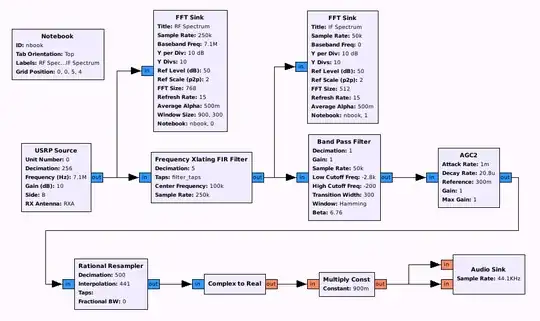
For an example, see this example in GNU Radio Companion by OZ9AEC. GNU Radio Companion can be a good source for examples because it's programmed by graphical flowcharts. Here's one from that article:

SSB receiver in GRC

There are some FFT Sinks which are graphical UI elements just to visualize the data at that point. USRP Source configures his particular hardware. The Frequency Xlating FIR filter performs the multiplication step, while additionally resampling the data (the USRP has a very high sample rate). Then there's a band pass filter, and he's added some automatic gain. Rational Resampler resamples the data again to get it down to an audio sample rate. Complex to Real discards Q and gives you just I. The multiplier at the end is a volume control, then it goes to the speakers.

Also if you look closely, the cutoff frequencies for the band pass filter are negative. As configured, this is an LSB receiver. Make those positive, and narrow, and you have a CW receiver.

user2338215
  • 226
  • 1
  • 6
Phil Frost - W8II
  • 52,635
  • 8
  • 91
  • 225
2

In my app “iSDR”, I approached SDR by the book, or more correctly books, using “An Introduction to Signal Processing and Fast Fourier Transform (FFT)" by Kevin J. McGee and "The Scientist and Engineer's Guide to Digital Signal Processing" by Steven W. Smith, Ph.D. (which is available on-line for free). The old QST series of articles titled "A Software-Defined Radio for the Masses" parts 1-4 by Gerald Youngblood, AC5OG was also very helpful. Taking bits and pieces from all of the above, iSDR implements CW receive as follows.

The baseband I and Q signals are fed one into each side of a complex FFT. The FFT results are then shifted to bring the desired center frequency bin (minus the CW offset) to the zero position (DC). Then a pre-calculated frequency-domain sinc (brick wall) filter is applied to the contents of the FFT. The inverse-FFT function is then applied giving back the time-domain shifted and filtered audio.

Doing the filtering in the frequency domain is very efficient since most of the calculations are performed ahead of time. So this approach even allowed the old Apple iPod touch second generation device to do a convincing (if suboptimal) job of demodulating CW, SSB, and AM signals. CW is the simplest, since CW signals simply "fall right out" of the above approach without any additional massaging of I and Q.

If any of the terms used in the second paragraph sound like mathematical gobbledygook, take a look through the references in the first paragraph. The math isn't simple, but it is extremely powerful. The few steps described in the second paragraph result in a remarkably sharp and clear receiver. iSDR provides a very usable CW filter as narrow as 100 Hz, and could easily be made narrower, except that centering it on the signal of interest becomes a challenge.

user2338215
  • 226
  • 1
  • 6