I need some help interpreting some information from my antenna analyzer (RigExpert AA-35). I want to use the information to impedance match my AM receiving antenna system to AM radios. No transmitting, just receiving. The data was captured at the point just before the feed-line enters the radio. 75Ω coax is used & was programmed into the analyzer. Here is the data that the analyzer provided:
- Freq in kHz = 511.2
- SWR = 2.62
- RL dB = 6.98
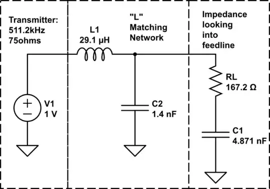
- Z (Ω) = 167.19 - j63.91
- |Z| (Ω) = 178.99
- |rho| = .045, phase = 19.95 (Degrees)
- C (pF) = 4871.47
- Zpar (Ω) = 191.62 - j501.28
- Cpar (pF) = 621.08
- 1/4 Cable Length = 317.47'
Q1: How do I convert the above data to provide the impedance of my antenna, at this point, for this tested frequency?
Q2: Then, how many ohms, increase or decrease, would be required to “transform” from the antenna impedance, so it becomes the 75Ω expected for input to the radio?
How these two answers are arrived at using the figures provided by the analyzer and the known requirements of the radio would be most helpful, so I understand the process.
I was under the mistaken impression that this impedance number would be provided in ohms by the analyzer in the same simple manner in which say the SWR is given. Trying to learn this process and hoping that being provided “how” this answer is achieved will help me understand how to use the analyzer for this purpose.
Just for reference, the antenna is an “IP33 MIni Whip Antenna”. Connected to 75 Ω coax. Connected to the systems small power amp for the whip (Unplugged). Connected to another short length of the 75 coax. The analyzer was at this point connected to the system. The same point where the antenna lead is converted to enter the back of the radio. I have measured at other points in the system. Just used this point as the example.
This question is not really about location placement of any actual transformer or Balun or Unun that might be installed. I am just using the above example to understand the impedance data acquisition and conversion for use in impedance matching. Thanks!


