6

I'm in the "information gathering" phase of a RF Power Meter project and the design I fancy (W7ZOI Power Meter) calls for a feed-through capacitor at the output port.

enter image description here

I understand that a feed-through capacitor is essentially a "trap" or low-pass filter that is typically employed to reduce RF emissions through enclosures. They look a little like this in chassis-mount format:

enter image description here

The thing is, they're not particularly common these days and tend to be expensive in my part of the world, especially when you include shipping.

So, I have a couple of questions:

Is there a more modern approach that RF designers use to isolate RF within metal enclosures?

Has anyone tried to emulate a feed-through with basic cheaper components (I'm thinking capacitors, coils and perhaps co-ax)?

Jack K6JEB
  • 157
  • 6
Buck8pe
  • 989
  • 5
  • 17

2 Answers2

5

Feed-through capacitors are still commercially available but their use in commercial applications has fallen off so prices have risen over the last few years. The concept with the feed-through capacitor was to provide an RF capacitive bypass to ground while providing a stout connection through the wall of the enclosure. When I see them at a swapfest for a reasonable price, I always pick them up for future projects.

In your application, the purpose of the feed-through capacitor is to keep RF that may be present on the connection to the DVM from feeding back into the signal conditioning electronics. If you do not plan on using a DVM with your version, you can eliminate this connection all together.

If you do wish to use the DVM connection, you can readily substitute an equal value capacitor connected as closely as possible to the entrance to the enclosure and grounded to the enclosure. You can enhance the bypass effect with a few ferrite beads of type 31 or 43 material or even a small toroid of the same material with a few turns of hookup wire wrapped through the center of the toroid. Position the beads or toroid as close to the entrance to the enclosure as possible.

You could perhaps improve the RF immunity by converting this connection to a shielded cable connector but most handheld DVMs only have "banana" style connectors so you would still introduce the possibility of RF being conducted into the conditioning electronics. Professional bench or rack type DVMs often offer a BNC style connection. If this is your case, then a shielded connector and cable would further improve the RF immunity of the conditioning electronics.

When it comes to keeping RF out of sensitive electronics a "belt and suspenders" (aka belt and braces) approach is a best practice. The more preventative measures, the better the results.

Glenn W9IQ
  • 18,688
  • 1
  • 25
  • 55
3

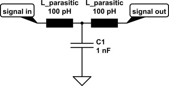
The reason to use a bypass capacitor instead of a simple capacitor to ground is that you'd typically want to keep the series inductance to ground as low as possible. So take this model of a capacitor with parasitic series inductors:

schematic

simulate this circuit – Schematic created using CircuitLab

and make it something more like this:
schematic

simulate this circuit

(values not representative and also not equal between forms)

Leaded capacitors really have a problem acting as pure capacitor at high frequencies, simply because the leads have a high degree of inductance themselves.

Therefore, elegant engineers came up with capacitors that you simply "wrap" around your signal line and "insert into ground"; your photo shows an excellent example of that. An example data sheet of different kind of three-terminal capacitors can be found here.

With the ubiquity of SMD components and cheaply available PCB manufacturing (e.g. oshpark.com), parasitic inductivity in shunt capacitors lost their edge – as long as your working on "benign" frequencies (which this sub-GHz power meter does).

So, this is 2018: get yourself a download of KiCad, and input the schematic in there. Layout the matching board, using the relatively well hand-solderable 0805 size of components. Unlike the design from the article, you'd be able to have signal lines well-surrounded by ground planes with plenty of vias.

That should eradicate the need for feed-through capacitors. If you still feel like having one: I don't deem 0.11 € to be especially expensive, which you'd pay for an SMD feedthrough cap.

There's good tutorials on working with KiCad; oshpark directly accepts kicad board files.

As a bit of personal commentary on the article:

I think that the calibration they did is insufficient; and the resulting dynamic range they promise hence overstated.

I'd personally would say: Buy a used power splitter from a measurement company (seems a bit more trustworthy than their thick passives in a box approach). Then, go and design a circuit around one of the plenty existing RF power meter ICs – it's going to be in the same order of complexity as the device from the article you cited, but you solve a whole lot of sources of inaccuracies right from the beginning.

Which one you pick would really depend on the frequency range you're considering; I don't know if the device presented in the article is exactly the span you care about.

I'd probably tend towards using a Texas Instruments LMH2110, as that really needs minimal external circuitry to measure powers.

Marcus Müller
  • 18,064
  • 26
  • 50