12

Capacitive hats seem to be advertised as an option for mobile vertical antennas. One mentioned advantage is the they can widen the SWR bandwidth, making the antenna easier to tune.

What might be the effect of using capacitive hats, not on a mobile vertical, but symmetrically on both ends of a wire dipole, or a shortened dipole?

Since wind loading isn't as much of an issue on non-mobile wire antennas, it seems almost any size capacitive hat might be possible by using arbitrarily large sheets of conductive wire screen material (hung or inside toy hoops, etc.). How might varying the size of the capacitive hats (from tin-can lid to patio door size) change the antenna's characteristics? (SWR, SWR bandwidth, radiation resistance, pattern, and etc.)

Added: Other than an increase in wind loading, is there any downside? Why shouldn't every dipole have a little conductive disk (or more) at the end?

hotpaw2
  • 13,635
  • 8
  • 49
  • 83

4 Answers4

6

Capacitive end loading has the effect of electrically "lengthening" a dipole (i.e. tunes it to a lower frequency). Similar to mid-loading with an inductor but with 3 notable differences:

  1. Capacitive loading is less lossy
  2. Capacitive loading has higher bandwidth
  3. Capacitive loading raises the radiation resistance more than an equivalent inductive loading

Potential downsides, other than mechanical issues such as wind loading: There are none.

Why shouldn't every dipole have a little conductive disk (or more) at the end?

For dipoles already tuned to the proper frequency, I would answer "they do not need it". For other cases... it gets difficult to describe so please see the flow chart below.

dipole decision tree

Summary: Best case would be a full size, half-wavelength, tuned dipole. But if there is a wire length restriction for whatever reason, adding a set of "cap hats" is truly a no-brainer.

In the case of a normal dipole that does not "need" capacitive end loading, there may still be a case for adding small "tin can lids" to the end --and, of course, shortening the wire a little to keep the tuned frequency constant. I cannot cite the reference, but it seemed to state that adding slight capacitive end loading like this gave a slight increase in radiation resistance. For "fussy" people such as me, this is enough to encourage adding cap hats to all of my otherwise-perfect dipoles. Unfortunately, I cannot cite that reference, did not memorize the optimal cap hat size, have not verified independently, and do not know how to measure radiation resistance.

Chris K8NVH
  • 1,062
  • 1
  • 10
  • 24
5

A capacitance hat used on a shortened antenna ($\le$ 1/8 λ for verticals and $\le$ 1/4 λ for dipoles) converts a largely triangular current distribution with the maximum current at the feedpoint, to a more uniform current distribution or alternatively, it lessens the peak current in the antenna element. This has the effect of:

1.) Raising the Rr (radiation resistance) of the antenna and thus improves the efficiency of the antenna.

2.) It helps to neutralize the inherent capacitive reactance of the shortened antenna and thus generally makes matching the antenna to the feedline an easier task.

Like all shortened antennas, the bandwidth of the antenna is typically less than a "full size" version of the antenna. But the hat will generally broaden the bandwidth compared to other methods of matching the antenna.

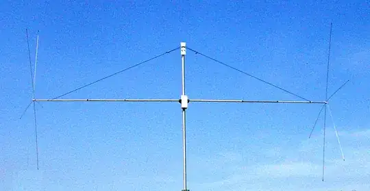
The concept of capacity hats on dipoles is not new. Here is a picture of a commercial dipole from DX Engineering. Note the clearly visible wire hats:

enter image description here

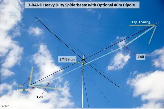
Here is a photo from DJ0IP showing his 40 meter cap hat dipole below his spider beam:

enter image description here

The classic modeling approach is to treat the antenna (or in the case of a dipole, each leg) as an open ended transmission line in order to calculate the impedance magnitude of the antenna (or the leg). The degree of wavelength of the antenna (or leg) is also computed. These values allow the reactance that is required to make up the "missing degrees" of the antenna element. Finally, the capacitive reactance required in the capacitance hat is computed. The following universal reactance curve for an open or shorted transmission line is used to compute the reactance required based on the missing degrees:

enter image description here

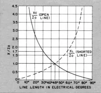
source: QST, September 1978, Designing a Vertical Antenna by Walter Schulz K3OQF

Inspection of the above diagram shows that if the element is a full 90° (1/4 wavelength) in length, then the transmission line effect will transform the infinite impedance of the open end to a near zero impedance (with near zero reactance) on the opposite end. For any electrical length in-between, the ratio of capacitive reactance to impedance is depicted. If the antenna is of simple wire construction, an impedance calculator such as https://chemandy.com/calculators/round-wire-impedance-calculator.htm may prove sufficient to determine the initial impedance magnitude of the wire. The commonly used formula for calculating impedance magnitude is:

$$Z_{MAG}=60(ln\left(\frac{2L}{r}\right) -1) \tag 1$$

where L is the length of the antenna or the leg of a dipole and r is the radius of the conductor, both in the same units.

The capacitance of the capacitive hat can be approximated from:

$$C_{pF}\approx0.89D \tag 2$$

where D is the diameter of the capacitance hat in inches.

Equation 2 is a reasonable approximation for circular capacitance hats constructed with plates, meshes or skeletal elements (e.g. spokes with a circumferential wire). It is important that the radius of the capacitance hat be <0.1 wavelengths so that the hat does not become a radiating element rather than strictly a capacitor at the end(s) of the antenna.

The capacitive reactance of the hat in ohms is given by the standard capacitive reactance formula:

$$X_C=\frac{1}{2\pi fC} \tag 3$$

where f is the frequency in hertz and C is the capacitance in farads.

Glenn W9IQ
  • 18,688
  • 1
  • 25
  • 55
0

To elaborate, the free-space, far-field directivity of a linear, 1/2-wavelength-long, center-fed, perfect dipole varies from that of an "infinitesimal," linear, center-fed, perfect dipole only by about 0.4dB.

However the gain of each of those configurations depends on the ratio of radiation resistance to the sum of radiation resistance with all other heat-dissipating, ohmic losses present in the antenna system.

Those other losses typically are larger for Z-matched antenna systems using loading coils, traps, and/or "capacitance hats" with electrically short radiating conductors — which system gain may be reduced by many decibels from that when using a "full sized," unloaded radiator.

[Reference: Antennas, 3rd Edition, Kraus/Marhefka, pp 23-26].

Richard Fry
  • 2,950
  • 8
  • 19
0

I installed a 40m dipole, having just enough space in my yard. I cut it to length as per the formula, so resonance should have been close… I used 12 gauge insulated wire. As a test, I installed 4 x 18” wire radials on each end to see the effect. Using an antenna analyzer, I was surprised to see that resonance was down around 6.200 mhz. I replaced the 4 wire radials I improvised, with a larger 3 leaf clover shaped cap hats, made with steel wire, fastened the cap hat to the wire using split nut connectors and soldered the ends of the dipole to the cap hat. The dipole resonated somewhere in the upper 5 mhz range. I then shortened the wire from the middle to bring it close to resonance on 40m. At the moment, the antenna resonates around 7.350 mhz , SWR is 1.2/1.3 @ R=50 ohms. After I trim it a bit, the dipole should be about right. On my first contact with a person I had spoken to before, he was surprised that I was now coming in 25+ over…. The overall length on my dipole, with the hats, is now roughly 50'ish ft. The size and shape of the cap hats will determine the final length of your dipole. With out over thinking capacitor hats, size, shape or equations, etc… just try it. I would say that in no way does using capacitor hats become a compromise to the signal in any way, if anything, it will likely greatly improve the efficiency of the dipole you have.

Best regards, Rene VE6DAY