2

I am trying to figure out how to go about using this LCA717 SPST-NO relay in my project. I will be sending 12V (car voltage) to a radar detector and I want to be able to turn it on/off whenever via the Digital Pin on an Arduino board (max 5V output).

As in, when the digital pin is high it allows 12v to flow to the radar. When the digital pin is low then it shuts out the 12V so no power is going to the radar.

enter image description here

But the problem is that I have no idea what to use for pin 5? Or if pin 4 and 6 are the correct pins to use to do what I am looking to do above?

The LCA717 PDF is here

enter image description here

JYelton
  • 34,119
  • 33
  • 145
  • 265
StealthRT
  • 743
  • 3
  • 12
  • 31

2 Answers2

3

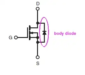
To understand the rationale of AC/DC and DC-only configurations, MOSFET body diode should be considered. In power MOSFETs bulk is connected to source, and that creates a diode in parallel with the MOSFET channel.

The picture below is from the datasheet of IRF510. It's a generic power N-channel MOSFET.

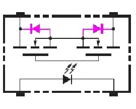
The picture below is from the datasheet of G3VM (another SSR). It also shows body diodes. [Highlighted by me.]
enter image description here

Due to body diode, the N-ch MOSFET can "open the switch" only when body diode is reverse biased. Drain has to be at a higher potential than the source. Otherwise, the diode will conduct, and MOSFET becomes a switch, which doesn't open.

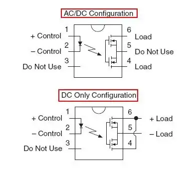
But what to do with the AC? During one part of the AC waveform, the body diode will be forward biased, during another part of the waveform, it will be reverse-biased. This is why the second MOSFET is used. The MOSFETs are connected in series such that their diodes are anti-parallel. They block each-other, and the MOSFETs can "open the switch" at all times. This capability to handle the AC comes at a cost, though. The two MOSFETs are in series and the losses are double.

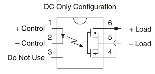
The LCA717 datasheet doesn't show body diodes. But the body diodes are there nonetheless.

enter image description here

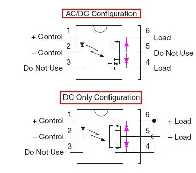
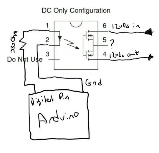
The designers of LCA717 decided to connect the MOSFET sources to the pin. It makes this SSR more versatile. It allows to connect the MOSFETS both: in series (AC/DC configuration), or in parallel (DC-only configuration). Notice that in DC-only configuration, the body diodes are in parallel too, and both of them can become forward biased. Notice that DC mode can handle twice the current.

enter image description here

On the other hand, the designers of the G3VM decided not to connect the MOSFET sources to the pin. Perhaps, they have done that to have fewer pins, in order to keep the device more compact and to keep the cost lower.

Nick Alexeev
  • 38,181
  • 17
  • 100
  • 237
  • So after all of that... does that mean it wont work for what i am looking to do? Cause too much heat? – StealthRT Oct 23 '13 at 20:55
  • Don't know. Is 2A or 4A current rating sufficient? How much current will your load need? – Nick Alexeev Oct 23 '13 at 21:03
  • its 12vdc and the plug (cig. lighter style) has a fuse of 2a so i am guessing its a max of 2A for that. – StealthRT Oct 23 '13 at 22:02
  • @StealthRT Then, 4A would be a sufficient current rating for the SSR. Consider also what Andy wrote in his post about the absolute maximum voltage this SSR can block (30V). Car's electric system can have nasty transient spikes, even though it's called "12V". – Nick Alexeev Oct 23 '13 at 22:20
  • the name is Andy actually and is that my picture you kidnapped to embellish your answer. I wouldn't mind normally but it's the same question you're answering. Is this common practise on EE? – Andy aka Oct 23 '13 at 22:25
  • @Andyaka Apologies, Andy. It was a brain slip. I've corrected the name. I wouldn't speak for the common EE practice. The picture is originally from the SSR's datasheet. You've added a few things to it. I've further added a few things myself. I don't see much of a conflict in this case. Nevertheless, I would gladly remove from the picture the red frames, which you artfully drew, if you so insist. Let me know. – Nick Alexeev Oct 23 '13 at 22:36
  • @NickAlexeev will the LCA717 need a heatsink? I have heard that since the On-State Resistance is 150 mOhm that it will need one? – StealthRT Oct 23 '13 at 23:48
  • @NickAlexeev No it's OK. Importance is the answer and not me. – Andy aka Oct 24 '13 at 07:31
  • @NickAlexeev will the LCA717 need a heatsink? I have heard that since the On-State Resistance is 150 mOhm that it will need one? And does the Arduino digital pin have enough juice to switch it on/off? – StealthRT Feb 27 '14 at 00:33
2

Here is what the data sheet recommends: -

enter image description here

The first configuration can be used for DC but it is better to use the 2nd configuration because you get lower "ON" resistance meaning there is less volt-drop to the load.

The device is trying its best to give you the best of both worlds.

Be aware that if you are using it in your car you should consider that the absolute maximum voltage it can block (pin 6 to pin 5) is 30V and this sounds a bit low for cars - there can be a lot of voltage spikes. Easy way around this is to put a zener diode across the device rated about 20V, 5W - excess spikes will get shunted to the radar detector and presumably this is OK working on a car power system so it'll cause no damage. Maybe even consider a 100nF capacitor as well.

Andy aka
  • 456,226
  • 28
  • 367
  • 807