0

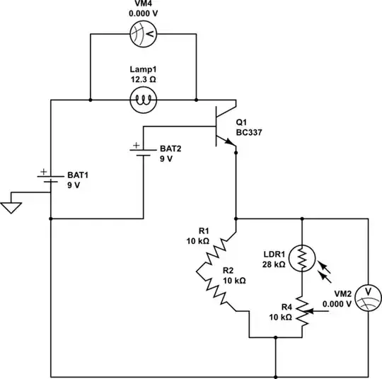
I am trying to switch on a load by using a Wheatstone bridge and planning to provide the differential voltage to the transistor.

Before doing that, I am trying to use two batteries (second one substituting the differential voltage from transistor).

However, I am getting a 0 V across the load and all of 9 V across the Wheatstone bridge.

schematic

simulate this circuit – Schematic created using CircuitLab

When I remove the transistor, I get 8 V across the bridge, but 0 across the load.

schematic

simulate this circuit

Either way, it's not turning on the light bulb or even a LED.
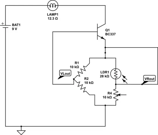
Final objective

Trying to switch on the load when the room gets darker (as resistance of LDR increased).

At ambient room light, I have set the Wheatstone bridge to be balanced or output a negative voltage.

As the darkness increases, resistance of the LDR increases, making the Wheatstone bridge un-balanced.

In our case, the voltage divider on right side (VRout), will decrease as R4 will remain constant whereas LDR1 will keep increasing.

At the end, the differential voltage between, VLout-VRout >=0.7V .

By connecting VLout to the base of an NPN transistor and VRout to ground, I am trying to switch the transistor to active state, in turn switching on the light bulb.

schematic

simulate this circuit

Null
  • 7,603
  • 17
  • 36
  • 48
Simsons
  • 123
  • 1
  • 1
  • 6
  • 1
    This circuit shows that you do not know how transistors work. Sorry. I have 2 suggestions: S1) search for twilight switch schematics S2) learn qualitatively how the voltages and currents in a transistors should be and go and how one can in practice produce a base current that controls the collector current. Your circuit has no way to feed base current through the base emitter joint. The base current Ib must be got from the battery through a light dependent network - preferably it has another transistor for enough tresholding and hysteresis. Ib cannot come from emitter, the voltage is reversed. –  Jan 22 '22 at 10:46
  • Why the down vote? Would appreciate if there is related explanation. Thanks ! – Simsons Jan 22 '22 at 10:59
  • @user287001, appreciate. Yes, there are so many variables when starting out , just trying to get a feedback from the community while I am trying to figure out. – Simsons Jan 22 '22 at 11:00
  • 1
    Here's the simplest possible on LDR based circuit. The tresholding is made with a relay - it needs a certain current to pull. The hysteresis (=no blinking near the treshold) is also caused by the relay - it holds with a smaller current https://www.electronicszone.it/testing/crepuscolarswitch_en.php The relay can be changed to a transistor circuit. The hysteresis ican be got if you essentially make the system a circuit which is usually called "Schmitt Trigger" –  Jan 22 '22 at 11:15
  • Thanks, will give it a try. @user287001 – Simsons Jan 22 '22 at 11:18
  • The potentiometer R4 will just act as a simple 10K resistor as you have not connected the wiper (moving contact) to anything. – Peter Bennett Jan 22 '22 at 17:23
  • 1
    @Simsons One of the very first questions that comes to mind (for me) when considering such an application, is to wonder about the purpose of the lamp, itself. Obviously, you want it on when it gets dark. But what is it supposed to achieve? Just an indicator? Or does it need to illuminate something? How much illumination is it supposed to provide, if so? The lamp is the key function here and it interacts with human perception and intent. So all of the details of what it is supposed to achieve are needed, first. That's job 1. The selection of an LDR and a schematic concept are way down the list. – jonk Jan 23 '22 at 02:55

2 Answers2

2

enter image description here

There are too many reasons why your circuit fails.

  1. Lack of low impedance current loop.
  2. Lack of differential bias threshold for each Vbe = 0.7V (consider 0.6 your bridge reference +/-0.1 for gradual ON/OFF)

This design I made solves both but is still weak due to the relatively low resistance of the bulb compared to the battery ESR for a Panasonic Alkaline which all have a wide tolerance, based on the short circuit transient current.

The Threshold is around 1.4V and the resistance of the Rce of the driver NPN for a PN2222A is around 1 Ohm depending on saturation current. I used a 3.3W 9V bulb to match your bulb R which rises from 1.2 ohm to around 11x this value near 2/3 A.

Adjust R ratios for night Vbe=1.4V and 1.2V to minimize battery drain in daylight.

Corrected design enter image description here

In order to turn on 12 to 14 ohm lamp with 10 k pullup to base, LDR must be much higher and the current gain must be much greater than this R Ratio of almost 1k. so two transistors in series as a Darlington, as shown above. These hFE's current gains multiply to enable saturation (low Vce) where the current gain is reduced to nearly 10% of rated hFE. Otherwise Vce rises until the gain is achieved.

In your case, the emitter resistance was far too high to conduct and bulb current to ground and back thru the batter to the bulb (even if Vbe was sufficient) So no bias voltage and no low R current loop.

Final remarks

A good alkaline battery can store 5 watt-hours [Wh]. A 9V bulb with these resistances cold and hot is a 3 W bulb. The battery will have a very short life and LED's are far more efficient.

There is no better design result than this one, if you restrict it as requested with BJT's, 12.3 ohm tungsten lamp at 9V with a battery and have no other requirements.

Tony Stewart EE75
  • 1
  • 3
  • 54
  • 185
  • I am using these bulbs from amazon and by claculation R should be 12.3 ohm, but using a multimeter , I get 1.2 ohm. Considering multimeter reading varies with external factors , updating the post to reflect 12.3 ohm. – Simsons Jan 22 '22 at 07:52
  • Both are accurate cold and hot – Tony Stewart EE75 Jan 22 '22 at 07:54
  • @Simsons I get, at operating temperature, that $R=\frac{\left(6.15:\text{V}\right)^2}{3:\text{W}}\approx 12.6:\Omega$. From this resistivity curve for tungsten, and just picking an operating temperature that experience suggests to me, I find that the cold resistance would be about $\frac{12.6:\Omega}{\frac{70}8}=1.44:\Omega$. So I don't see any problems with your measurement. I can't say I understand exactly what you are trying to achieve. Could you write more in your question to help out? What are you really trying to achieve here? – jonk Jan 22 '22 at 08:04
  • @jonk, have updated the question with final objective and more detail. – Simsons Jan 22 '22 at 09:09
  • @Simsons Why does a Wheatstone figure into this? It is so much easier to just set up a nice hysteresis circuit and be done with it. I'm confused why all this trouble to use wheatstone, in particular. – jonk Jan 22 '22 at 09:25
  • @jonk, I am just practicing along the theory and trying to make sense of why things don't work the way I expect and where am I going wrong. – Simsons Jan 22 '22 at 09:30
  • @Simsons You start with the two end points: the sensor input and the lamp output. The sensor (LDR) spans over several orders of magnitude. The output (lamp) spans over about one magnitude of resistance, hot vs cold. I'm between, you need some hysteresis (adjustable) and a light/dark setpoint. For the output, you need a lamp driver. This bounds your options. Yes? Where does the wheatstone arrive in all this? I'm not saying it cannot. But I want to hear your thinking. – jonk Jan 22 '22 at 09:42
  • @jonk, to turn on the transistor, I need to apply a base voltage >=0.7v at base of transistor. I could do that by using the same battery or another battery. But I am trying to use the differential voltage from the Wheatstone bridge to provide the require .7v to the base of transistor. But clearly, I am doing something wrong. – Simsons Jan 22 '22 at 10:57
  • 1
    @Simsons You just need a differential amp (long tailed pair) of BJTs. You can then easily add hysteresis to that and use its output to drive another simple circuit to supply the lamp current. There are other options that are a little more subtle. So that's not the only approach. But it is certainly one you should learn about, because it applies to almost every opamp you will ever see in your life as well as applying to this problem. – jonk Jan 22 '22 at 19:15
  • Thanks , will get onto it @jonk – Simsons Jan 23 '22 at 00:21
  • 1
    Simsons there is insufficient gain from one transistor . I showed one inverting solution. If you need hysteresis then you need to cascade 2 inverting stages to make hysteresis. Simple. Right @jonk ? This demands very high gain and low resistance drive. – Tony Stewart EE75 Jan 23 '22 at 02:00
  • 1
    @Simsons For example, look here. – jonk Jan 23 '22 at 02:25
  • 1
    @Simsons But keep in mind that you aren't going to get half an amp out of a typical 9 V battery. Worse, is that the current will be still higher when cold if you just use a switch circuit. You could current limit things, but then that's more circuitry and thought and doesn't fix the 9 V current limit. But the first thing you need to decide about is whether or not you will retain the incandescent lamp and its high current requirements. If you keep the lamp, you need a different power supply. If you let go of the lamp, then you may be able to keep the 9 V battery. Which is more important to you? – jonk Jan 23 '22 at 02:42
1
  1. Your transistor is an emitter follower.

    A BJT is not controlled by the base terminal. It is controlled by the base terminal and emitter terminal relative to each other.

    BAT2 is referenced to GND and therefore applies voltage to the base relative to ground. However, the base relative to the emitter is what the transistor cares about. It does not know or care what you have defined ground in your circuit to be. It cannot see that ground because it has no terminals connected to it. It only cares about what's between the base and emitter.

    So imagine your transistor does conduct. Current flows through your wheatstone bridge causing a voltage drop across it which makes the voltage of the emitter node relative to ground rise. If you are applying a ground referenced voltage to the base, the the base voltage relative to ground remains the same while the emitter voltage relative to ground rises. The end result is that the difference between base and emitter gets reduced, potentially to the point where the transistor can no longer conduct enough to do its job. Negative feedback. The more it conducts the more it resists conducting further.

But that point is moot because you have more fundamental issues with your circuit:

  1. You have a short-circuit across your lamp. So your lamp will never turn on.

  2. Your "wheatstone bridge" makes no sense in a bunch of ways. The voltmeter put across isn't what you do for a wheatstone bridge, but even bigger is that you said you are trying to use your wheatstone bridge to switch a lamp. Wheastone bridges don't switch anything. They measure. Transistors switch things, but it was already established your transistor was wired up incorrectly, but even if your transistor was wired up correctly it has nothing controlling the base-emitter that would cause switching to occur.

    I know you say BAT2 is a temporary stand in for a differential voltage to feed to the transistor. However, I see nowhere from which you can derive that in your circuit nor do I see how you plan to apply a differential voltage to a single transistor.

You might want to go back to the drawing board for this one. Start simple with one function (like just switching on the lamp manually) and and build the circuit up to the functionality you want. It looks like you skipped a few steps and fumbled along the way.

DKNguyen
  • 56,670
  • 5
  • 69
  • 160
  • @DKNguyen , was over sight, removed the short circuit now. – Simsons Jan 22 '22 at 07:05
  • 1
    @Simsons Alas, I am not sure the other issues will be so simple to fix. Well the next fix would just be to remove wheat-stone bridge from the emitter of the NPN. That would move the NPN from a high-side switch to a low-side switch where they work best and simplest. The wheatstone bridge or sensing substitute for it to control the transistor will need to go elsewhere. The wheatstone-bridge is largely unsuited though since it provides a differential output but a transistor setup that can accept a differential output requires many, well-matched transistors (normally in a comparator or OpAmp IC) – DKNguyen Jan 22 '22 at 07:22
  • @DKNguyen, Thanks , looks like some more reading to do . Will do. – Simsons Jan 22 '22 at 07:32